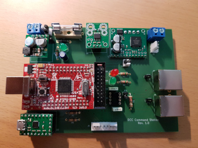
The Command Station is at the heart of the DCC Control System. It generates the DCC signal to control locomotives and other decoders, and provides a power interface (up to 20V and 3A) to send the signal to the rails.
It also provides 3 extension mechanisms:
- A CAN bus to connect with the other modules (remote control, network interface, presence detectors…)
- A 3-pin header with the logic DCC signal to control boosters
- A 8-pin header with SPI signals reserved for a future use
Hardware (version 1.0, March 2020)
Schematic
The schematic is available:
This first version uses several ready-to-use boards to make the development easier:
- An Olimex STM32-H405 board: the main microcontroler (an STM32F405)
- A Pololu 5V 2.5A Step-Down Voltage Regulator (#2858): generates the 5V voltage to power the components of the board from the track voltage (10-20 V)
- A Pololu MC33926 Motor Driver Carrier (#1212): generates the signal to be sent to the rails from the logical DCC signal produced by the microcontroler
- A Pololu ACS714 Current Sensor Carrier -5A to +5A (#1185): measures the consumption on the tracks
- A Pololu CP2104 USB-to-Serial Adapter Carrier (#1308): connects the board to a PC in the absence of the Network Interface
PCB
License
The hardware project is licensed under the CERN-OHL-Pv2.
Software
The firmware is available on GitLab: https://gitlab.com/guiduc/dcc/-/tree/master/command_station/firmware
Features
The version 0.1 (August 2020) is very limited: it only sends DCC commands to one locomotive at a fixed DCC address (3). It receives orders from the remote control via the CAN bus or from a PC via the UART using a simple protocol.
Roadmap
The roadmap for future versions is available in the README
License
The firmware is licensed under either of
at your option.
